
OVERVIEW
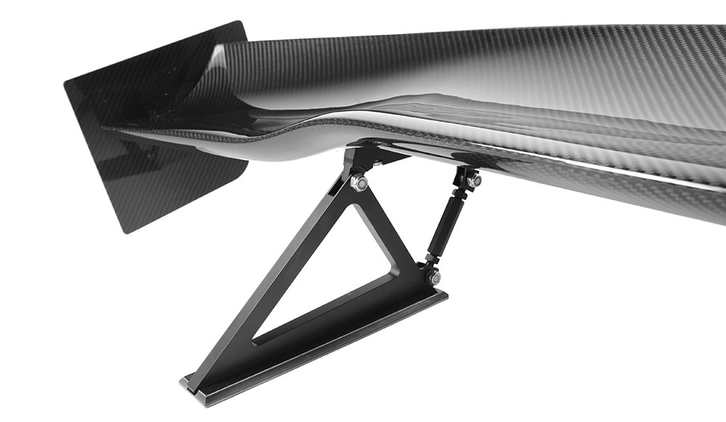
Spanning 60.5 inches over its optimized 3D airfoil shape, the APR Performance New GTC-200 Adjustable Wing supplies maximum downforce in midsize and compact car applications.
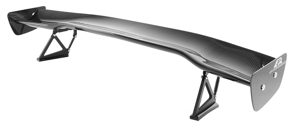
GTC-200 Adjustable Wing
The Downforce Balance graph (shown at the left) illustrates which areas of the vehicle this product affects.
There are three (3) areas: Front, Center, and Rear. The size of the red bar represents how much this product affects each particular area.
BENEFITS
SPECIFICATIONS
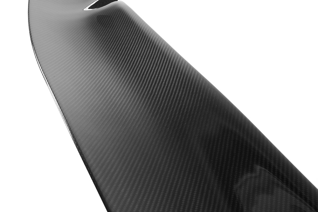
| Pattern | 2x2 twill weave |
| Material | Pre-preg carbon fiber, 3K |
| Coating | UV-stable clear coat |
| Wing Span | New: 60.5" w/ variable Angle-of-Attack (AOA) (center section vs outer section angle difference: 14 degrees) original: 59.5" w/ variable Angle-of-Attack (AOA) (center section vs outer section angle difference: 12 degrees) |
| Hardware | Stainless-steel machine screws, washers, and nuts |
| Mounting | 6061 billet aluminum brackets/pedestals with application-specific bottom mounting bases |
FEATURES
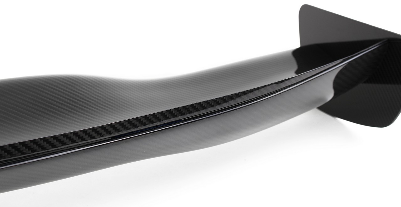
The APR Performance New GTC-200 Adjustable Wing features a 3D airfoil shape that is designed to produce balanced downforce across its span on midsize and compact car applications.

Each GTC Series airfoil is composed of lightweight and durable pre-preg carbon fiber composite materials for superior strength and low weight.
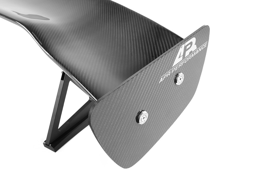
Aerodynamically-tuned side plates (aka end plates), included with every GTC Series Adjustable Wing, are critical components that help to ensure consistent airflow across the full span of the airfoil.
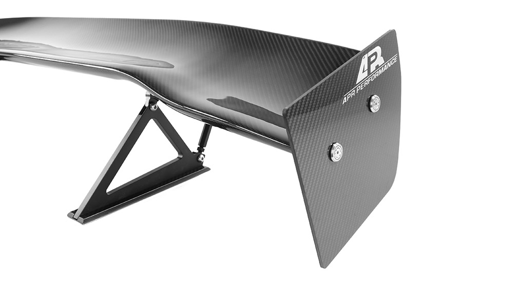
Supporting the airfoils are 10mm "aircraft grade" 6061 billet aluminum pedestals that come in a flat black powder coat finish.
Computational Fluid Dynamics (CFD)
Modeled in 3D and validated using Computational Fluid Dynamics (CFD), the APR Performance New GTC-200 Adjustable Wing is designed to adapt to a variety of midsize and compact car applications.
CFD Data for the New GTC-200 Adjustable Wing (Click to View)
OVERVIEW
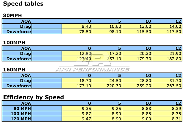
Contained herein are the data and results of the Computational Fluid Dynamics (CFD) analysis that was conducted on the New GTC-200 airfoil. This data illustrates how the airfoil performs in different conditions by comparing Downforce vs. Angle-of-Attack (AOA) vs. Speed, and Drag vs. AOA vs. Speed. This data will provide insight with regards to how and how much the airfoil performs with respect to these conditions.
To learn how to interpret and apply this type of CFD data, see sample analysis on the GTC-300 page.
DATA (w/o Gurney)

DATA & RENDERINGS (w/ Gurney)


The information contained herein is property of APR Performance, and may not be reproduced in whole or in part without prior written consent from APR Performance.
CFD Data for the original GTC-200 Adjustable Wing (Click to View)
OVERVIEW
Contained herein are the data and results of the Computational Fluid Dynamics (CFD) analysis that was conducted on the original GTC-200 airfoil. This data illustrates how the airfoil performs in different conditions by comparing Downforce vs. Angle-of-Attack (AOA) vs. Speed, and Drag vs. AOA vs. Speed. This data will provide insight with regards to how and how much the airfoil performs with respect to these conditions.
To learn how to interpret and apply this type of CFD data, see sample analysis on the GTC-300 page.
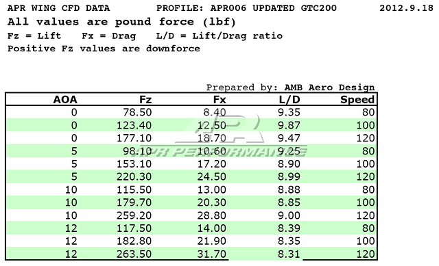
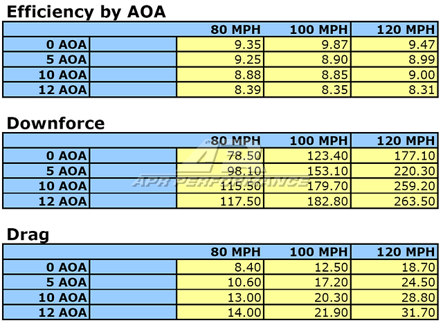
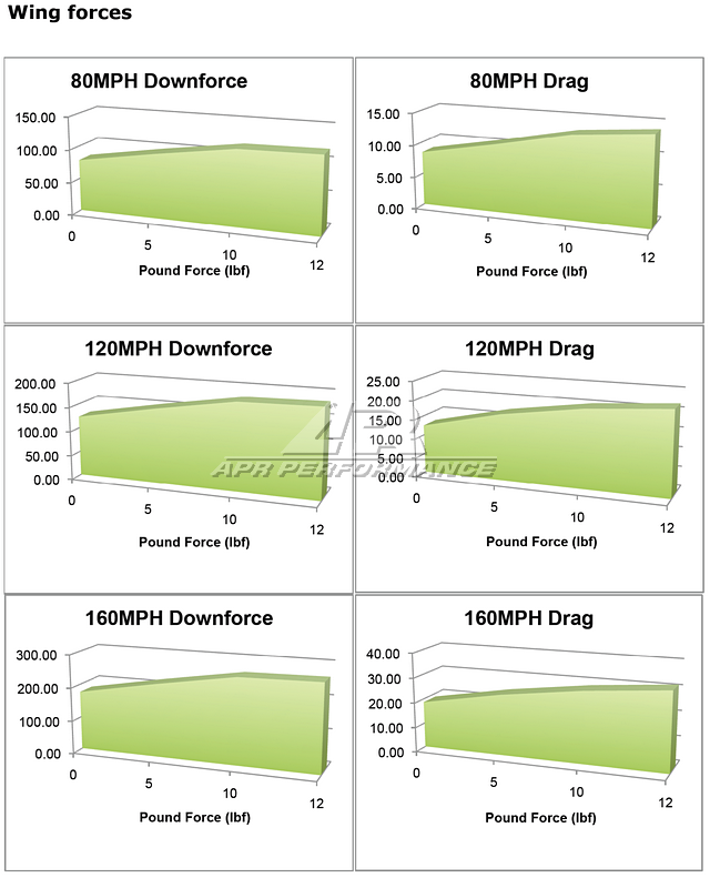
CFD DATA (TABLES)
The following table shows the actual data that were collected from the CFD analysis (w/o Gurney flap). The numbers in the table are represented in Newtons (a unit of force). To convert to "pounds," divide the numbers by 4.44822 (where 1 Newton (N) = 4.44822 Pounds-force (lbf)). For example, a downforce of 1286.89 N would equal 289.3 lbf.

The following image illustrates where and how the AOA is referenced. At 0 degrees AOA, the reference plane is parallel to the direction of the free air stream (the stream would travel from right-to-left in this image). This reference plane can be simulated by placing a ruler across the top of the center section of an actual airfoil.
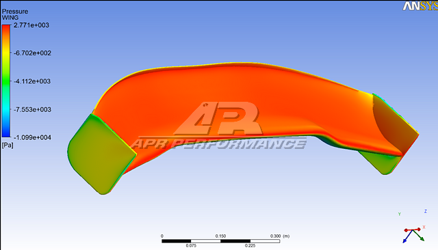
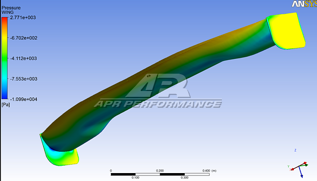
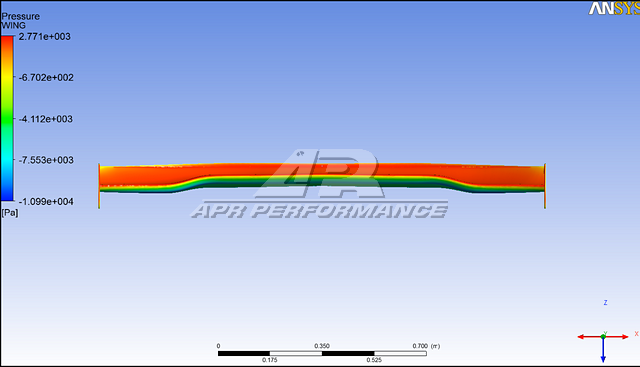
CFD DATA (RENDERED IMAGES)
The following image illustrates the pressure distributions across the surfaces of the airfoil (w/ Gurney flap). The units are in Pascals (Pa), where 1 Pa = 1.45 x 10^-4 Pound Per Square Inch (lb/in^2).
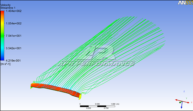
The following image illustrates both the pressure distribution and streamlines associated with the airfoil (w/ Gurney flap).
The following image illustrates both the pressure distributions and vector fields around the airfoil (w/ Gurney flap).
The information contained herein is property of APR Performance, and may not be reproduced in whole or in part without prior written consent from APR Performance.
Gurney Flaps
Gurney flaps are available for all APR Performance GTC Series (200/300/500) wings. These are super lightweight, made using pre-preg carbon fiber processes, and conform perfectly to the contours of the GTC series 3D airfoils. They are easily attached using the included double-sided tape.
History of the Gurney Flap (Click to View)
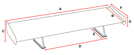
Wing Dimensions
Measurements for the GTC-200 Adjustable Wing (same for New and original models) are shown in the table below. Pedestal-to-pedestal distances are indicated for standard applications. Custom pedestal-to-pedestal distances can be accommodated for custom applications.
Wing Dimensions Table (Click to View)
| A | B | C | D | E | F | G | ||
|---|---|---|---|---|---|---|---|---|
| GTC-200 Universal | % | # | 10.0" | 29.5" | 6.25" | 9.5" | 5.5" | |
| GTC-200 SCCA Spec. | 48" | # | 10.0" | 29.5" | 6.25" | 9.5" | 5.5" | |
| Acura RSX 2002-2006 | % | # | 10.5" | OEM | 7.25" | 9.5" | 5.5" | |
| Ford Mustang S197 2005-Up | % | # | 10.0" | OEM | 7.25" | 6.0" | 6.0" | |
| Honda S2000 2000-Up | % | # | 10.5" | OEM | 7.25" | 9.5" | 5.5" | |
| Lotus Elise 2002-Up | % | # | 10.0" | 19.0" | 7.25" | 4.5" | 4.5" | |
| Lotus Exige 2007-Up | % | # | 10.0" | 19.0" | 7.25" | 4.5" | 4.5" | |
| Mazda Miata 1990-2005 | % | # | 10.5" | 40.0" | 7.25" | 9.5" | 5.5" | |
| Mazda RX-8 2004-Up | % | # | 10.5" | OEM | 7.25" | 9.5" | 5.5" | |
| Mitsubishi Evolution 8/9 2003-2007 | % | # | 10.0" | OEM | 9.0" | 10" | 7.5" | |
| Mitsubishi Evolution X 2008-Up | % | # | 10.0" | OEM | 9.0" | 9.5" | 5.5" | |
| Subaru Impreza WRX 2002-2007 | % | # | 10.0" | OEM | 7.25" | 9.5" | 5.5" | |
| Toyota Celica 2000-2005 | % | # | 10" | OEM | 7.25" | 9.5" | 5.5" | |
| Special Notes: %Wingspan original GTC-200: 59.5" New GTC-200: 60.5" #Variable cord length original GTC-200: 8.50" Inner Max / 6.75" Outer Max New GTC-200: 9.50" Inner Max / 6.75" Outer Max |
||||||||
Notice
Effective September 5, 2013, the New GTC-200 foil replaces the original GTC-200 foil. All orders as of this date have been shipping with the New GTC-200 (except for the SCCA application, which will continue to come with the original GTC-200 foil).
New GTC-200 vs original GTC-200 (Click to View)
- Larger chord than the original GTC-200.
- More aggressive camber than the original GTC-200.
- Higher lift/drag (L/D) ratio than the original GTC-200.
- More downforce than the original GTC-200.
- Backwards compatibility with all original GTC-200 mounting brackets and pedestals.
Applications
Vehicle-specific and custom applications are listed below.
Vehicle Applications (Click to View)
- Acura Integra
- Acura RSX
- BMW 1-Series
- BMW Z4
- Ford Mustang 1996-2004
- Ford Mustang 2005-2009
- Ford Mustang 2015-17
- Ford Mustang 2018-Up
- Honda S2000
- Lotus Elise
- Lotus Exige
- Mazda Miata
- Mazda RX-8
- Mitsubishi Lancer Evolution 10
- Mitsubishi Lancer Evolution 8
- Mitsubishi Lancer Evolution 9
- Scion FR-S
- Scion tC
- Subaru BRZ
- Subaru WRX / STI 2002-2003
- Subaru WRX / STI 2004-2005
- Subaru WRX / STI 2006-2007
- Subaru WRX / STI 2011-2014
- Toyota Celica
- Toyota GT-86 2017-Up
Special Application: Drag Style (Click to View)

Custom Applications: Universal Style (Click to View)
Custom pedestal-to-pedestal distance, built-to-order. Standard-height pedestals are used.

Warning
User assumes full responsibility for ensuring proper installation as intended. Professional installation by well-qualified personnel is highly recommended. The vehicle applications shown above are intended to work as a complete system when installed onto original vehicle body parts (i.e. trunk lids, hatches, etc.). To insure proper function and reliability, APR Performance advises against modification or substitution of any component of the intended installation. Any modification or substitution of the airfoil, side plates, pedestals, mounting bases, mounting brackets, or hardware included with the wing kit may create unsafe operating conditions and ultimately cause this system to fail. Substitution of original vehicle manufacturer parts needed for the intended installation (i.e. rear trunk lid or rear hatch) with non-original parts may also create unsafe operating conditions and ultimately cause this system to fail.